
Electric current Ohm’s law and Resistance
Electrical current is the flow of charged particles. The flow of charges will be constant in current electricity. Electric current flows from higher electric potential to lower electric potential. For the current to flow, it requires a circuit which is closed loop of a conducting material. The circuit consists of wires which are connected end to end and the electrons flow in same direction.
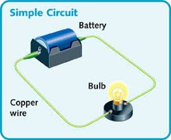
A circuit has conductors (wire), switch, load and a power source. The circuit starts and stops at the same point. Usually copper wires are used as conductors without insulation. It is through the conductor the current flows. A switch is used to open or close the circuit. When the switch is closed current flows through the circuit and when the switch is open, it breaks the circuit and no current flows through it. A cell can be the power source. If we put more than one cell it becomes a battery.
The load which is also known as Resistor uses the electrical energy and converts it into some other form of energy. It can be a light bulb or anything else. If there is no load in the circuit then it will be a short circuit.
Electric Current is measured in amperes (amps) by an ammeter which will be connected in series with other components in a circuit. Current, I = Q / t, where Q is the charge in coulombs and t is the time in seconds.
Voltage is defined as the electrical potential difference between two points in a circuit. The unit of voltage is volts. The unit is derived from the name Alessandro Volta. Cells or batteries provide the voltage or the potential difference which is required.
Resistance resists the flow of current. It is the measure of an objects ability to hold off the flow of electrons. The resistance will be low in a conductor and high in an insulator. It is measured in ohms. The unit ohm is named after the scientist Georg Simon ohm who formulated the ohm’s law.
Resistors are used to control the flow of electric current in a circuit. It converts electrical energy into heat and light. A resistor is a passive component as they consume power but will not generate power. They are usually made up of metal, carbon or with metal oxide film. Resistors are used for limiting the current and to protect the semiconductor devices like LED. It is also used to limit the frequency response in a filter circuit.
Ohm’s Law
Georg Simon Ohm showed the relationship between voltage, current and resistance and formulated the ohm’s law. This law is the basis of electricity.
The law states that V = I R, where voltage V is in volts, Current I in amps and resistance R in ohms.
Thus I = V / R and R = V / I.
Series and Parallel Connections
There are mainly two types of circuits, Series and Parallel. Both series and parallel circuits consists of more than one load. Resistors can be connected both in series, parallel or a combination of both.
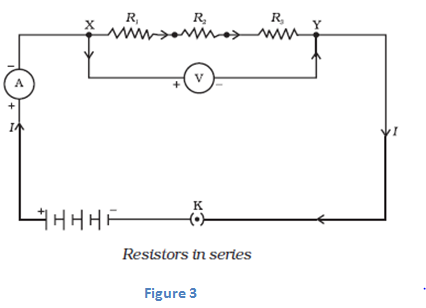
In series circuit electrons travel only in one path. Here the current will be the same which passes through each resistor. The voltage across resistor in a series connection will be different. In series connection if one resistor is broken or any fault occurs, the entire circuit is turned off. Series circuits do not overheat easily. The design of series circuit is simple compared to parallel circuits.
- In brief, When two or more resistances are connected end to end then they are said to be connected in series combination.
Some Christmas tree lights can be in series circuits. If one bulb goes off the entire string goes out.
In parallel circuit electrons travel through many branches in it. In this case the voltage remains the same across each resistors in the circuit. Here the current in the circuit is divided among each branches and finally recombines when the branches meet at a common point. A parallel circuit can be formed in many ways, which means resistors can be arranged in different forms. It can be used as a current divider.
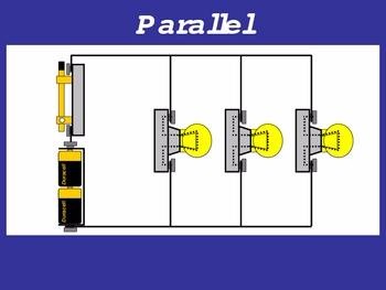
- In brief, When two or more resistances are connected between the same two points they are said to be connected in parallel combination.
In most cases the circuits are connected in parallel. This is because if one resistor is broken or damaged, it won’t turn off the entire system. But due to this effect, it is difficult to detect the failure if anything goes wrong in the circuit and thus it can be dangerous at certain times. It is easy to connect or disconnect a new resistor or other component without affecting the other elements in the parallel circuit. But it uses a lot of wires and hence becomes complex. Mostly in buildings and houses we use parallel connection.
A third type of circuit involves the dual use of series and parallel connections in a circuit; such circuits are referred to as compound circuits or combination circuits. The circuit depicted at the right is an example of the use of both series and parallel connections within the same circuit. In this case, light bulbs A and B are connected by parallel connections and light bulbs C and D are connected by series connections. This is an example of a combination circuit.
Ohms Law Example
For the circuit shown below find the Voltage (V), the Current (I), the Resistance (R) and the Power (P).
Voltage [ V = I x R ] = 2 x 12Ω = 24V
Current [ I = V ÷ R ] = 24 ÷ 12Ω = 2A
Resistance [ R = V ÷ I ] = 24 ÷ 2 = 12 Ω
Power [ P = V x I ] = 24 x 2 = 48W
CGPCS Notes brings Prelims and Mains programs for CGPCS Prelims and CGPCS Mains Exam preparation. Various Programs initiated by CGPCS Notes are as follows:-